Hollow Glen – Starting your model train layout

Trevor Holloway who built and runs the exhibition layout Hollow Glen has kindly put together information on how to get your own layout up and running as well as giving an introduction to the hobby.

Please Click here to download the PDF file

You will need Adobe Acrobat Reader to view the file which can be downloaded from https://www.adobe.com/au/acrobat/pdf-reader.html

Please note the advice provided is solely that of the author and does not necessarily reflect the views of the Waverley Model Railway Club.

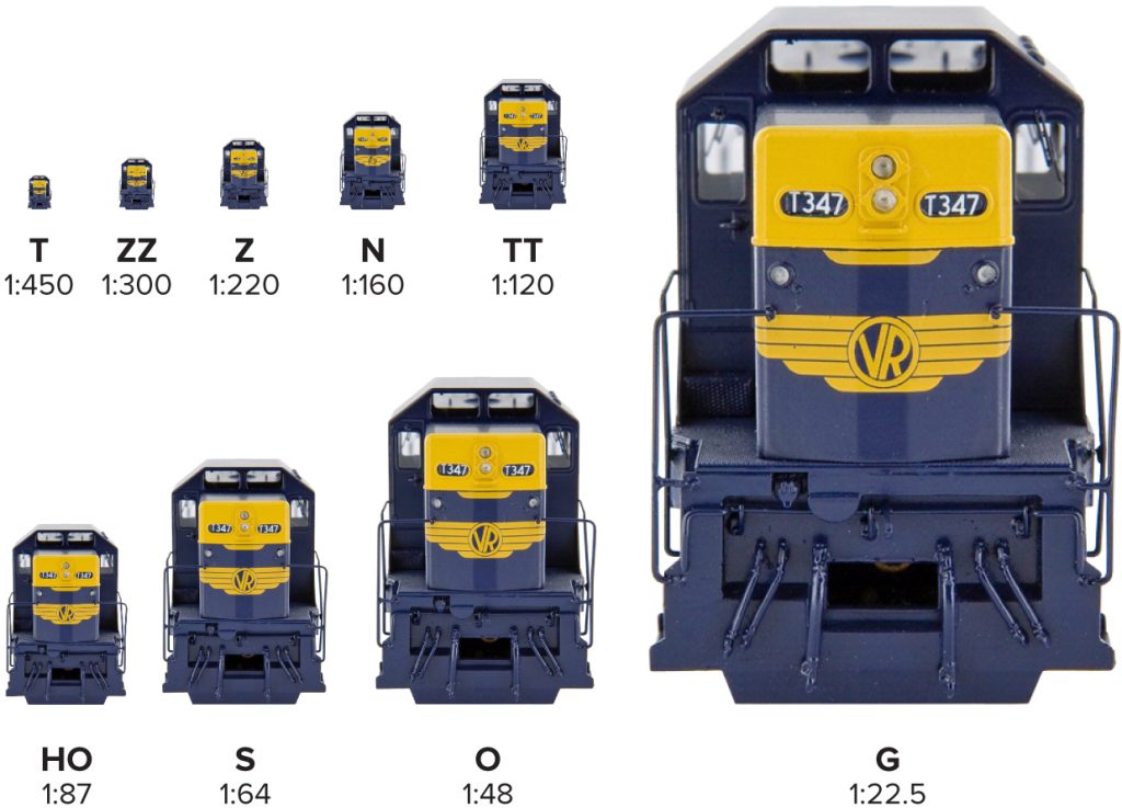
Scale and Gauge

The following is a basic description courtesy of Australian Model Railway Association Inc.

scale-guide

Scale

The ratio between the size of the models and the size of the prototype. This can be expressed either as a ratio or as so many millimetres per foot (or fractions of an inch per foot for American models).

Gauge

The distance between the rails. Standard gauge is 1435mm (4 foot 8-1/2 inches) or the equivalent distance scaled down on the model. Anything narrower than this is called narrow gauge and anything wider is called broad gauge. In most cases the actual gauge used on the model varies slightly from the correct distance when scaled down from the prototype. Refer to AMRA’s prototype gauge chart for actual gauges used in various parts of the world.

Scale name

Each popular scale is given a name (alpha and/or numeric code) which indicates, not only the scale to which the model railway / railroad model is being built, but also gives an indication of the track gauge used. The actual scale and gauge associated with a given name may vary depending on the prototype being modelled. In the case of narrow gauge the names also usually give an indication of the gauge of the prototype being modelled. See AMRA’s standard and narrow gauge tables.

Orientation

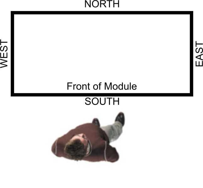
When facing the module, the module’s front edge is SOUTH, the back edge is NORTH, the edge to your left is WEST and the edge to your right is EAST.

standards-module-orientation

Example 1

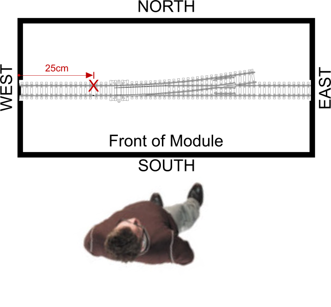
Describing a physical problem on the layout: There is a broken solder joint on the NORTH rail, 25cm from the WEST edge.

standards-module-orientation-example-1

Example 2

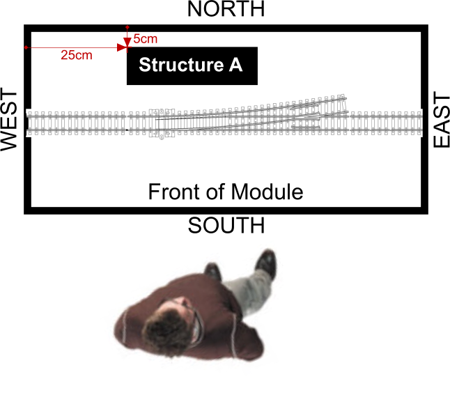
Referencing the Position of a structure: The NORTH wall of Structure A runs parallel to the NORTH edge of the module. The NORTH WEST corner of Structure A is 5cm from the NORTH edge and 25cm from the WEST edge.

standards-module-orientation-example-2

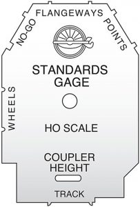
Useful tools